Thursday, 22 December 2016
Renesas RX62N: Transmitting data from UART/RS-232 through DMA
Here is an example I created on how to use DMA on Renesas RX62N for transmitting RS-232/UART data. Link
Friday, 9 December 2016
Implementing a Custom DHCP Server (with customizable DHCP Router IP field) on Windows CE on Wi-Fi adhoc connection
Recently, we had a requirement from a customer:
1. Our Windows CE device must be able to host an adhoc network.
2. It must have a DHCP server and it must provide a Router IP of 0.0.0.0 to the client (iPhone or iPad).
Adhoc Network on Windows CE
Luckily, Windows CE can do Adhoc Network connection. An iPhone can connect to it. However, whenever we connect a USB WIFI dongle, we always get a UI for setting up Wifi connection. The way to suppress this is by disabling it on the Platform Builder.
Second, the quickest way to establish an Adhoc connection programatically is by using the open-source OpenNetCF library. But since we are using a NET CF 2.0 device, I ported the OpenNetCF from 3.5 down to 2.0. It works very well.
DHCP Server with Router IP 0.0.0.0
The reason why our customer needs 0.0.0.0 is because it must be able to connect to 3G while Adhoc is connected and this is the only known way to do that.
At first, we used the built in DHCP allocator of Windows CE but it doesn't return Router IP of 0.0.0.0 no matter what we do (or maybe there are some registry settings that we missed). But the problem is the source code for this is not available.
What I did is I implemented a DHCP server on Windows CE. There is a desktop C# DHCP server that I saw on CodeProject. I ported it to .NET CF 2.0 and it works. I can now modify the packets. I can now set the Router IP to 0.0.0.0. BUT... the DHCP works only if the ActiveSync cable is connected. This is how I was able to solve it:
I did some investigation using WireShark and I can see that UDP/DHCP packets are not being sent when ActiveSync cable is not connected. On the file clsUdpAsync.cs, the function public void SendData(byte[] Data) will send a SocketException error regarding DNS whenever the ActiveSync cable is not connected. Digging further, I noticed that there are overloaded BeginSend function on UdpClient class. One of the functions has the parameter hostname and whenever we call that, it requires some NS resolution even if your input to the function is "255.255.255.255" which is a broadcast address. One function has a parameter IPEndPoint and just require IPAddress object. I used that and everything worked perfectly.
I forked it, rectified the SendData function and placed it on my Github account. Link
Wednesday, 23 November 2016
Saturday, 8 October 2016
TThread: Achieve Basic Concurrency, Real-Time Systems without using RTOS on any microcontroller
I previously worked in an automotive industry, and the way we did concurrency on a non-RTOS system is through case switches of time in multiples of 2^n:
case 1: // 1 millisecond
case 2: // 2 millisecond
case 4: // 4 millisecond
case 8: // 8 millisecond
case 16: // 16 millisecond
case 32: // 32 millisecond
... so on so forth
But as the program grows, we found that we need to implement many internal state machines and it could be problematic in terms of maintenance and code readability (because we need to jump from one place to another to figure out the flow of the program). But this is still one of the techniques that I may use someday.
I had been using TThread years ago and I think this is a good way to achieve concurrency. It doesn't have the heaviness of an RTOS and although it doesn't have the full features of an RTOS, it is very space efficient, it works, and can be used on any microcontrollers (note: it should have at least a timer interrupt)! Here is one of my personal project in Arduino which is all about a concurrent, real time system which does the following:
1. pulsed laser for theft detection
2. trip wire for theft detection
3. water level monitoring for flood detection
Written in C++ (and with abstraction/polymorphism), Source code here:http://codepad.org/cb1H2QAa (This is just a hobby code and everything was written on 1 file because Arduino IDE doesn't play well with multiple files) . On this code, I made some modifications on the TThread code to be able to accomodate up to more than 254 lines of code.
Credits to the author of TThread. http://www.microchipc.com/sourcecode/tiny_threads/tthread.h
Protocol Buffer in C++: Building, Using ProtoC and Creating an Application for Visual Studio 2015 Community Edition
Part 1
Part 2
Part 3
Saturday, 24 September 2016
Replacement Dell Charger Not Recognized! (Autopsy of the TF2929 1-Wire Protocol EEPROM)
3 days ago, an error message popped-up on my laptop after the BIOS screen and it says Unrecognized Power Adapter like the one I found on this link. I checked the system properties and I saw that my Intel-i7 is running at 760MHz!!! No wonder my Embedded Linux compile time is very slow! With this, I opened the AC adapter and I saw this chip TF2929. Upon checking the datasheet, it is a 1-wire EEPROM. I took this out and created a 1-wire protocol software on Arduino Mega.

I created a very simple 1-wire software to detect the presence of the EEPROM. And looking at my oscilloscope.

The TF2929 doesn't respond. Explanation: On the datasheet of the EEPROM, it says there that after a Reset Low Time (in this case, it is 488microseconds), the EEPROM should respond 15 to 60microseconds after the rising edge of the Reset Low Time. As seen here, there is no reply from the TF2929 and I am confident that it is dead. Frustratingly, I can't do much at this point. Even if I buy a new TF2929, I don't have the binary file to be written to the EEPROM.
I even checked the laptop and I can see that it is sending pulses but the TF2929 doesn't respond as well. (Sorry, no screenshots) Therefore, the laptop's 1-wire master is working fine and I don't need to do anything on the mainboard.
The question now is why it happened. This is how it was implemented.

Open-drain circuits can fail and one of their symptoms is that they couldn't sink any current and I had seen this happen. It is possible that the TF2929 can receive messages but it can't respond back because their open-drain output has been damage. If I'm the engineer in charge for this circuit, I will make it like this:

Wherein R is around 50ohms and/or not lower than 22 ohms.
Now, the only feasible thing to do at this point is to buy a replacement 90W AC adapter.
Update: Sept 25, 2016
I bought a second hand Dell 90W AC Adapter for 7 US dollar. All my findings above are correct. Now my laptop can recognize the 90W Adapter and is now running again on full speed.
Monday, 19 September 2016
[Repair] Dell Vostro Replacement AC Adapter improvements
- mild electric shock
- interference on audio recording (mic or guitar)
Prerequisites are:
- soldering iron
- wire
- properly grounded outlet
Saturday, 17 September 2016
Cross-Compiling and Debugging C++ program on BeagleBone Black Embedded Linux using Windows (+ debugging using gdbserver / gdb)
Here is a short video of me doing a demonstration on how to Compiler and Debug C++ Program on a BeagleBone Black using Windows machine.
Sorry for the low quality audio. I will invest on a good mic in the future.
Saturday, 10 September 2016
Passing tips (HOW TO): Passed the Prince2 (Project Management) Foundation and Practitioner Exam through Self-Study
This year I was able to obtain both the Foundation and Practitioner certification in Prince2 Project Management. On this post, I will give some tips on how to pass both exams.
I enrolled at ILX Group for the online training course for both the Foundation and Practitioner exam. They also sent me an official copy of the Prince2 manual. I will assume on this post that you will be enrolling at any training centers that provides online training courses/material.
Preparing for the Foundation exam:
On taking the Foundation exam, you will be given an hour and if you are prepared for this exam, you will be able to pass it. As there are no negative markings, don't leave any blanks. Next, Practitioner exam.
Preparing for the Practitioner exam:
On taking the Practitioner exam, you will be given 2.5 hours maximum. But it can be finished earlier (I finished mine around 1.5 hours). During the exam, they will allow you to take 5 minutes break (although I didn't take any breaks during my exam). Before you begin the exam, they will ask you if you would like to print the exam scenario and please PRINT IT so that you won't need to flip back-and-forth on the scenario and questions page. Since you already have the project scenario printed, you can concentrate on the questions. Also bring some water, some light snacks (peanuts,sweets) as the 2.5 hours will be intense. Again, don't leave any blanks as there are no negative markings.
Good luck!
I enrolled at ILX Group for the online training course for both the Foundation and Practitioner exam. They also sent me an official copy of the Prince2 manual. I will assume on this post that you will be enrolling at any training centers that provides online training courses/material.
Preparing for the Foundation exam:
- This is the first exam that you must pass before going to Practitioner.
- You will be needing the Prince2 manual for the Foundation review but I don't recommend reading it yet. I will discuss that later.
- First thing you need to do is to watch ALL the videos from the training provider. They will give you good insights on what Prince2 is all about.
- After you finish all the videos, do some tries on the exam simulator based from the knowledge you gained from the video tutorials. This will give you some insights on what are needed on the exam.
- From the exam, you will notice that you need to be familiar with some objective and purpose statements which comes from the official manual. Also, be aware on the structure of the questions. Watch out for negative questions (e.g. which of this IS NOT part of Starting Up a Project)
- Now, read the Prince2 manual. Concentrate on the Themes, Processes and Principles. Read the Appendix A as well.
- Then do at least 10 practices on exam simulator.
On taking the Foundation exam, you will be given an hour and if you are prepared for this exam, you will be able to pass it. As there are no negative markings, don't leave any blanks. Next, Practitioner exam.
Preparing for the Practitioner exam:
- From my opinion, Foundation exam is easy. But the Practitioner is a tough exam. Tougher than the Foundation exam by 10 to 20 times. So you might want to give yourself ample time to prepare for the Practitioner exam.
- First, go through and finish all the videos provided by the online training centers.
- Buy some sticker tabs and put them on your Prince2 manual. Put one sticker tab per section (starting from chapter1,chapter2.... up to glossary).
- At the end of the manual, I suggest you draw the Prince2 Process Model (it will clearly show you the flow of the processes, which products are created/updated on which process). Try searching for some Prince2 Process Model on the web.
- Read some sample papers and do some exam simulator practice.
- Same with foundation, be aware of the structure of the questions. Multiple choice with 1 or 2 answers, sequences, reason-assertion, matching type.
- Do some reading on the Appendix A as you will be required to know the sections of the documents (e.g. Business Case, End Project Report, Configuration Item Records).
On taking the Practitioner exam, you will be given 2.5 hours maximum. But it can be finished earlier (I finished mine around 1.5 hours). During the exam, they will allow you to take 5 minutes break (although I didn't take any breaks during my exam). Before you begin the exam, they will ask you if you would like to print the exam scenario and please PRINT IT so that you won't need to flip back-and-forth on the scenario and questions page. Since you already have the project scenario printed, you can concentrate on the questions. Also bring some water, some light snacks (peanuts,sweets) as the 2.5 hours will be intense. Again, don't leave any blanks as there are no negative markings.
Good luck!
Saturday, 20 August 2016
Pondering back on my project: Scalability of MVC architecture on Windows CE (with multiple Windows Forms)
In my project, there are 50+ UIs/View/Windows Forms, Data Layer SQL, Interop with another DLL, 3 product variants of the same software (heavy use of Strategy Pattern and Template Method Pattern on this), Cloud, XML/JSON/Protobuf Serialization and unique features based from the OEM variants of our product. I would say that this is a huge and complex project. And I have around more than 150+ source files where I had written 90% to 95% of the total code base. In that book, I saw that the Model was almost repeated on the Controller (but with the views references and manipulation). This has caused pain because of the redundancy just to achieve great separation of concern. I felt that the author's approach is ok on small projects, but I have great doubts on it on big projects unless you have all the time and resources to accomplish that (but we are on a small company and time is gold to us). So midway on the schedule of the project, I found myself refactoring a lot to keep everything under control and to keep the flames down.
With the aforementioned issues, I did more research and found articles regarding Skinny Controllers-Fat Model, Model-Mediator-GUI and MVP(in Supervising Controller). From there and based from the issues I faced, I was able to come up with this Model-Mediator-Controller-View (MMCV - which I coined the term by myself). This is still in current version and may still change, but I have confidence that this will solve most of the scalability issues that I had encountered. This is not yet final and I may modify it, depending on the circumstances that I may face.

Saturday, 6 August 2016
FreeRTOS on Renesas RX62N
Just recently, I would like to learn VxWorks. But with the cost of the license, I turned to FreeRTOS. I saw that it supports Renesas RX62N and luckily, I have the development kit.
I downloaded the latest software for Renesas RX62N (HEW,Segger, and other toolchain) as well as updating the GCC compiler. Then I used the information here http://www.freertos.org/FreeRTOS_RX62N_GCC_GNURX.html.
After opening the project on folder FreeRTOSv9.0.0\FreeRTOS\Demo\RX600_RX62N-RDK_GNURX , I was able to start working with it and was able to create tasks, implement mutexes,etc easily. I would say that it is almost the same with the MQX RTOS that I previously used in one of the RF products that I was involved with (except for the API syntax).
All my experiments are located here: https://github.com/fwswdev/RenesasRX62NFreeRTOSDemo
Monday, 30 May 2016
Weekend Project: 3D Printed 26dB Pre-amp Booster
This is my weekend project: a 3d Printed 26dB Preamp Booster. This uses a OPA2134 op-amp. Simulated and verified using LTSpice.


Tuesday, 16 February 2016
S Pen Digitizer (Source Code Fork)
Lately, I had been looking for a way to transform my Galaxy Note 2 into a graphics tablet. I stumbled into this open-source software, Link . It works, however on my first tries, I noticed that there are some unwanted offseting during drawing. I then forked the source code and debugged the code made changes to it. Now the unwanted offset has been fixed and I added a top-left calibration. The down-right calibration will be added in my free time.
Here is the forked source code with the fix Link
Despite of the quirks, I believe this is still a great idea/software by the original author. Thank you to https://github.com/artursgirons
Here is the forked source code with the fix Link
Despite of the quirks, I believe this is still a great idea/software by the original author. Thank you to https://github.com/artursgirons
Monday, 15 February 2016
Boost Smart Pointers
Nowadays, we have the luxury of having Garbage Collectors in C#, Java, Python, etc. But we don't have that luxury in C++. Nobody can deny that managing pointers is a good to have skill, however, things had changed, the technology evolved as well and we might as well delegate the handling of pointers to someone else. Enter Boost Library. This is a superb library with lots of tools. The smart pointers on Boost library can greatly reduce the risk of memory leaks. Let's see the following samples run on Visual Studio 2015 with the memory leak detector enabled.
class ABasePerson
{
public:
virtual void ShoutDescription() = 0;
};
class Fireman :public ABasePerson
{
public:
void ShoutDescription()
{
cout << "I am a Fireman!";
}
};
Above is a classic usage of polymorphism and we will use this as the basis of our example.
----------------------------------------------------------------------------------------------------------------
Example #1
{
ABasePerson *basePerson = new Fireman();
basePerson->ShoutDescription();
delete (basePerson);
}
This example will work well.
----------------------------------------------------------------------------------------------------------------
Example #2
{
ABasePerson *basePerson = new Fireman();
basePerson->ShoutDescription();
}
On this example, the developer forgot to delete the basePerson and now we have memory leak!
----------------------------------------------------------------------------------------------------------------
Example #3
{
boost::shared_ptr<ABasePerson> basePerson2(new Fireman());
basePerson2->ShoutDescription();
}
On this example, the basePerson2 will automatically be freed once it goes out of scope. Very convenient!
----------------------------------------------------------------------------------------------------------------
Example #4
boost::shared_ptr<ABasePerson> basePerson2(new Fireman());
basePerson2->ShoutDescription();
basePerson2 = NULL;
On this example, the basePerson2 will automatically be freed once it was set to NULL.
----------------------------------------------------------------------------------------------------------------
On this post, we saw the convenience of using Boost Smart Pointers.
Update: I am not using the Boost Smart Pointers as of the moment. Instead, I am using C++11's smart pointers since they are almost included in every compiler. (I use GCC in Linux and MSVC on Windows and they both include C++11's Smart Pointers)
Saturday, 13 February 2016
Arduino Signal Experiment #4: DC Offset Removal using Arduino
From my first post Arduino Signal Experiment #1, we can see that I added a DC offset so that Arduino will be able to measure the peak to peak signals of the sine wave that I am producing. Now, in this post, I will show how to simply remove that DC offset.
This is the code that I wrote for Arduino. http://codepad.org/A2ckv1ER
On the code, I reused the code that I wrote in Signal Experiment #1, but this time, I refactored it and placed it in a class that inherits from a base class with one abstract method. This way, it will be easier to experiment and add some more experiments. The class that we will be focusing on is the SamplingWithDCBiasRemoval class. After running the code, here is the resulting waveform:
As seen on the waveform, the DC offset was gone. Noticed the Gain value which I set to 0.8? Feel free to adjust that value and see what will happen on the waveform.
This is the code that I wrote for Arduino. http://codepad.org/A2ckv1ER
On the code, I reused the code that I wrote in Signal Experiment #1, but this time, I refactored it and placed it in a class that inherits from a base class with one abstract method. This way, it will be easier to experiment and add some more experiments. The class that we will be focusing on is the SamplingWithDCBiasRemoval class. After running the code, here is the resulting waveform:

As seen on the waveform, the DC offset was gone. Noticed the Gain value which I set to 0.8? Feel free to adjust that value and see what will happen on the waveform.
Friday, 12 February 2016
Arduino Signal Experiment #3-B: Goertzel using Arduino
On my last blog post, I discussed the library that I will be using on this blog post. We will be using the library that I forked and modified. Same as before, we will be using a PC speaker output going straight to an Arduino Mega. This is the arduino code that I used http://codepad.org/ezlp9tKT .
On Audacity, I generated two sine waves - 425Hz and 700Hz.

On Audacity, we can mute the channels to be able to verify if the Goertzel algorithm works.
Experiment 1 - Both Channels muted
Magnitude(425Hz): 15
Magnitude(700Hz): 11
Experiment 2 - 700Hz Active / 425Hz Muted
Magnitude(425Hz) 234
Magnitude(700Hz) 5984
Experiment 3 - 700Hz Muted / 425Hz Active
Magnitude(425Hz) 6299
Magnitude(700Hz) 152
Experiment 4 - 700Hz and 425Hz Active
Magnitude(425Hz) 4328
Magnitude(700Hz) 4243
If I adjust the master volume of my laptop, the Goertzel algorithm reports the change of magnitude. To conclude, we can see that the Goertzel Algorithm can detect and distinguish the target frequencies.
Special Thanks to jacobrosenthal.
Arduino Signal Experiment #3-A: Goertzel using Arduino
This is the third series of the Arduino Signal Experiment. Now we will be dwelving with Goertzel Algorithm. Before we go to the actual experiment (which I will be posting on the next blog), I will discuss the Goertzel library that we will be using this time. I searched for an Goertzel Library and I found this https://github.com/jacobrosenthal/Goertzel and from my initial experiment, this pretty worked well, however, I faced some hurdles when doing multiple tone detection. I therefore checked and forked the source code. After that, I did some modifications:
- I added a ChangeParameter to be able to dynamically change the parameters, thus no need to re-sample again. This contains the code that was initially on the constructor.
- All the global variables on the cpp files were pushed to the header files, making them class level variables. This way, if I choose to make two instances of Goertzel, then those variables will be instantiated. But since I already used a ChangeParameter, this second option may be rarely used.
Arduino Signal Experiment #2 FFT Analysis using Arduino
From the previous blog, we were able to see signals in the time domain. Now, we will try to analyze things in frequency domain. I will be using this FFT Library http://wiki.openmusiclabs.com/wiki/ArduinoFFT . To start with, I created three different sine waves on Audacity (I will be sticking to sine waves to avoid the unwanted harmonics of a square wave):

The three different sine waves are: 200Hz, 625Hz and 850Hz. I also opened the built-in Frequency Analyzer of Audacity for us to have an idea of what those 3 frequencies are.
This is the code that I wrote for Arduino http://codepad.org/UnFPb87k
On the code, notice that I used 450usec on the delay. This value is ideal for the 3 target frequencies that I will generate from Audacity and this is the explanation: The FFT bin size is 256. The output array will be FFT bin size divided by 2 (256/2 = 128). In this case, my array dimension is from 0 to 127.
@ array 0, index * (1/T) / binsize = 0 * (1/450usec) / 256 = 0 Hz
@ array 1, 1 * (1/450usec) / 256 = 8.680555555555555 Hz
@ array 2, 2 * (1/450usec) / 256 = 17.36111111111111 Hz
@ array 127, 127 * (1/450usec) / 256 = 1102.4305555555554 Hz
Which means, I will be measuring only up to 1102 Hz.
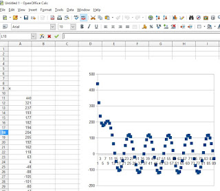
Now, after I played the tones and measured it using the Arduino program, I tried to plot the values using OpenOffice Calc:

We can clearly see that the FFT works as shown by the rise on the magnitude on 200Hz, 625Hz and 850Hz. :)

The three different sine waves are: 200Hz, 625Hz and 850Hz. I also opened the built-in Frequency Analyzer of Audacity for us to have an idea of what those 3 frequencies are.
This is the code that I wrote for Arduino http://codepad.org/UnFPb87k
On the code, notice that I used 450usec on the delay. This value is ideal for the 3 target frequencies that I will generate from Audacity and this is the explanation: The FFT bin size is 256. The output array will be FFT bin size divided by 2 (256/2 = 128). In this case, my array dimension is from 0 to 127.
@ array 0, index * (1/T) / binsize = 0 * (1/450usec) / 256 = 0 Hz
@ array 1, 1 * (1/450usec) / 256 = 8.680555555555555 Hz
@ array 2, 2 * (1/450usec) / 256 = 17.36111111111111 Hz
@ array 127, 127 * (1/450usec) / 256 = 1102.4305555555554 Hz
Which means, I will be measuring only up to 1102 Hz.
Now, after I played the tones and measured it using the Arduino program, I tried to plot the values using OpenOffice Calc:

We can clearly see that the FFT works as shown by the rise on the magnitude on 200Hz, 625Hz and 850Hz. :)
Arduino Signal Experiment #1 Sine Wave Input to Arduino using Laptop Speaker
Most of us who would like to do actual experiments for FFT or Goertzel algorithms using Arduino will need a simple signal generator to be fed into the analog pins of Arduino. We could buy some cheap signal generators from Ebay or Aliexpress, but there is a cheaper alternative that is already in front of you.... your PC or Laptop's Speaker output. In this blog post, I will show a step-by-step guide on how to use this.
Our PC or Laptop's speaker output has a DC offset of 0V(due to AC coupling) as seen on majority of audio designs. This means that the sine wave can reach down to negative voltage which is not an ideal input to Arduino since it will not be able to measure the negative voltages. To resolve this, the sine wave must have a DC offset to be able to read the positive and negative peak of the sine wave. Here is a simple circuit to do that:

On the simulation, we can see that the input V_speakerInput was offset to Vcc/2. On the actual circuit, the R4 must be removed since it was only placed here to act as a dummy load (some simulators have trouble simulating circuit without load). The R1 and R2 can range from 1K to 3K. The R3 can range from 100 to 470 ohms. Here is the actual circuit:

I am using the great Arduino Mega 2560 and I soldered the surface mount resistor and capacitor on a separate bare PCB board. As you notice, there is only 1 wire from the TRRS audio jack that I used. This is because I omitted the ground wire to avoid ground loop. I will just simply use the USB's ground as the main ground source of the circuit.
Next part is the software to generate the sine wave -----> the great open source Audacity. This is a beautiful piece of software which I use most of the time for music recording/composition. I never expected to use this someday on my engineering work as well. :) Going to back to our project, once you run Audacity, go to Generate menu > Tone and you can see that:

For the Arduino, here is the code that I am using currently using to verify if Arduino can read the sine wave (with DC offset) http://codepad.org/infZ2OLV
To prove that it works, I generated a sine wave tone on Audacity at 400Hz. I captured it using Arduino and graphed it:

Voila! A sine wave with DC offset. :)
Our PC or Laptop's speaker output has a DC offset of 0V(due to AC coupling) as seen on majority of audio designs. This means that the sine wave can reach down to negative voltage which is not an ideal input to Arduino since it will not be able to measure the negative voltages. To resolve this, the sine wave must have a DC offset to be able to read the positive and negative peak of the sine wave. Here is a simple circuit to do that:

On the simulation, we can see that the input V_speakerInput was offset to Vcc/2. On the actual circuit, the R4 must be removed since it was only placed here to act as a dummy load (some simulators have trouble simulating circuit without load). The R1 and R2 can range from 1K to 3K. The R3 can range from 100 to 470 ohms. Here is the actual circuit:

I am using the great Arduino Mega 2560 and I soldered the surface mount resistor and capacitor on a separate bare PCB board. As you notice, there is only 1 wire from the TRRS audio jack that I used. This is because I omitted the ground wire to avoid ground loop. I will just simply use the USB's ground as the main ground source of the circuit.
Next part is the software to generate the sine wave -----> the great open source Audacity. This is a beautiful piece of software which I use most of the time for music recording/composition. I never expected to use this someday on my engineering work as well. :) Going to back to our project, once you run Audacity, go to Generate menu > Tone and you can see that:
- You can generate Sine/Sawtooth/Squarewave
- You can set the amplitude and time duration
- You can even produce and mix different tones and play them all together!

For the Arduino, here is the code that I am using currently using to verify if Arduino can read the sine wave (with DC offset) http://codepad.org/infZ2OLV
To prove that it works, I generated a sine wave tone on Audacity at 400Hz. I captured it using Arduino and graphed it:

Voila! A sine wave with DC offset. :)
Thursday, 11 February 2016
MyHDL Project #2: Flexible Multiplexer Demultiplexer
https://github.com/fwswdev/MyHDLCollection/blob/master/02_FlexibleMuxDemux.py
This is a MyHDL program that contains multiplexer and demultiplexer. They both share a group of select pins. Users can change the number of mux and demux by just simply changing the BIT_WIDTH constant.
Few years back, I designed a UART Multiplexer/Demultiplexer using lots of 74HC4051. If I only knew MyHDL and XC2C128 by that time, my design could have been more compact. :)
MyHDL Project #1: Two Counters with 2 to 1 Multiplexer
Recently, I had been studying MyHDL with Xilinx CoolRunner XC2C128 CPLD. MyHDL is a very good software. I can simply reuse my existing Python skills and get started quickly with HDL designs.
https://github.com/fwswdev/MyHDLCollection/blob/master/01_TwoBlinkingLightsWith2to1Mux.py
This is a MyHDL program that has two counter (fast and slow) that outputs square waves. The counters are being controlled by a rising edge clock signal coming from a square wave signal generator (on my experiment, I used a 555 timer on astable mode). It is then fed into a 2 to 1 mux. This is tested working with XC2C128, Xilinx ISE 14.7, and Bus Pirate as the programmer.
This is the resulting test bench waveforms (I modified the internal counters to 5 and 10)

Special Thanks to this Online Wave Viewer http://www.edaplayground.com/w/home
Saturday, 16 January 2016
FileDB: a .NET NoSQL DB
http://www.eztools-software.com/tools/filedb/
This is a very good .NET NoSQL solution. Very lightweight. I did some example projects just for practice session using Visual Studio 2015 Community Edition. https://github.com/fwswdev/NoSQLPractice
This is a very good .NET NoSQL solution. Very lightweight. I did some example projects just for practice session using Visual Studio 2015 Community Edition. https://github.com/fwswdev/NoSQLPractice
Review: DX.com's 5A USB Charger

5V/5A (25W) USB Charger
Here is product that I bought from DX.com created by ZnDIY-BRY. Link
Recently, we have lots of devices in our home that uses USB chargers. But why did I build one?
- I know for a fact that there are USB chargers that have high current output. But some of them have very bad regulation. I bought a cheap USB charger for my mom, and it destroyed her Samsung Galaxy S3. I checked the charger and saw the voltage rise up to 5.6V at 1A, but I don't know the actual voltage when the scenario happened. We also bought from an unknown manufacturer and the voltage rises up randomly when the current draw is greater than 1A.
- Last year, I bought one product from ZnDiy-BRY, a 2 port USB charger 3A. This is a very good product. I use it in my office to charger my Galaxy Tab and Samsung Galaxy Note. Given this company's very good reputation, I bought their 5A, 4port USB charger.
- DIY and building is fun!
After I received the item, I did a very simple 3D printed bottom cover just enough to avoid the bottom part of the PCB to be in contact with our house floor.

Since this is a 25W (5V/5A) device, I chose a DC supply of 12V, 3A (36W). This is to give enough margin for the efficiency of the USB charger and the DC supply

In this test, I placed 4 devices that are in charging state - A Samsung Galaxy Note, Two Samsung Note 2, and a Sony Xperia C5. All of them are in charging state and none of them are in fully charged state. The voltage is at 4.93V on this test (my USB doctor have some issues, but if I use a multimeter, it is exactly 5V). Then, I touched the heatsink and I am surprise that there's not much heating at all.
In summary, I am very happy with this device. It passed my expectations. Now I can keep all our 220V to 5V chargers inside a cabinet and just use this superb 5A charger..
Subscribe to:
Comments (Atom)