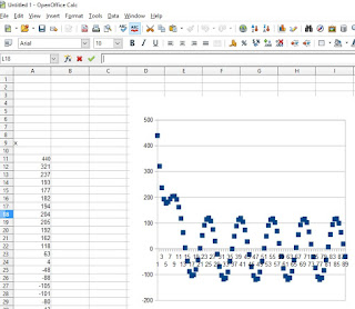
From my first post Arduino Signal Experiment #1, we can see that I added a DC offset so that Arduino will be able to measure the peak to peak signals of the sine wave that I am producing. Now, in this post, I will show how to simply remove that DC offset.
This is the code that I wrote for Arduino. http://codepad.org/A2ckv1ER
On the code, I reused the code that I wrote in Signal Experiment #1, but this time, I refactored it and placed it in a class that inherits from a base class with one abstract method. This way, it will be easier to experiment and add some more experiments. The class that we will be focusing on is the SamplingWithDCBiasRemoval class. After running the code, here is the resulting waveform:
As seen on the waveform, the DC offset was gone. Noticed the Gain value which I set to 0.8? Feel free to adjust that value and see what will happen on the waveform.

No comments:
Post a Comment