Lately, I had been looking for a way to transform my Galaxy Note 2 into a graphics tablet. I stumbled into this open-source software, Link . It works, however on my first tries, I noticed that there are some unwanted offseting during drawing. I then forked the source code and debugged the code made changes to it. Now the unwanted offset has been fixed and I added a top-left calibration. The down-right calibration will be added in my free time.
Here is the forked source code with the fix Link
Despite of the quirks, I believe this is still a great idea/software by the original author. Thank you to https://github.com/artursgirons
Tuesday, 16 February 2016
Monday, 15 February 2016
Boost Smart Pointers
Nowadays, we have the luxury of having Garbage Collectors in C#, Java, Python, etc. But we don't have that luxury in C++. Nobody can deny that managing pointers is a good to have skill, however, things had changed, the technology evolved as well and we might as well delegate the handling of pointers to someone else. Enter Boost Library. This is a superb library with lots of tools. The smart pointers on Boost library can greatly reduce the risk of memory leaks. Let's see the following samples run on Visual Studio 2015 with the memory leak detector enabled.
class ABasePerson
{
public:
virtual void ShoutDescription() = 0;
};
class Fireman :public ABasePerson
{
public:
void ShoutDescription()
{
cout << "I am a Fireman!";
}
};
Above is a classic usage of polymorphism and we will use this as the basis of our example.
----------------------------------------------------------------------------------------------------------------
Example #1
{
ABasePerson *basePerson = new Fireman();
basePerson->ShoutDescription();
delete (basePerson);
}
This example will work well.
----------------------------------------------------------------------------------------------------------------
Example #2
{
ABasePerson *basePerson = new Fireman();
basePerson->ShoutDescription();
}
On this example, the developer forgot to delete the basePerson and now we have memory leak!
----------------------------------------------------------------------------------------------------------------
Example #3
{
boost::shared_ptr<ABasePerson> basePerson2(new Fireman());
basePerson2->ShoutDescription();
}
On this example, the basePerson2 will automatically be freed once it goes out of scope. Very convenient!
----------------------------------------------------------------------------------------------------------------
Example #4
boost::shared_ptr<ABasePerson> basePerson2(new Fireman());
basePerson2->ShoutDescription();
basePerson2 = NULL;
On this example, the basePerson2 will automatically be freed once it was set to NULL.
----------------------------------------------------------------------------------------------------------------
On this post, we saw the convenience of using Boost Smart Pointers.
Update: I am not using the Boost Smart Pointers as of the moment. Instead, I am using C++11's smart pointers since they are almost included in every compiler. (I use GCC in Linux and MSVC on Windows and they both include C++11's Smart Pointers)
Saturday, 13 February 2016
Arduino Signal Experiment #4: DC Offset Removal using Arduino
From my first post Arduino Signal Experiment #1, we can see that I added a DC offset so that Arduino will be able to measure the peak to peak signals of the sine wave that I am producing. Now, in this post, I will show how to simply remove that DC offset.
This is the code that I wrote for Arduino. http://codepad.org/A2ckv1ER
On the code, I reused the code that I wrote in Signal Experiment #1, but this time, I refactored it and placed it in a class that inherits from a base class with one abstract method. This way, it will be easier to experiment and add some more experiments. The class that we will be focusing on is the SamplingWithDCBiasRemoval class. After running the code, here is the resulting waveform:
As seen on the waveform, the DC offset was gone. Noticed the Gain value which I set to 0.8? Feel free to adjust that value and see what will happen on the waveform.
This is the code that I wrote for Arduino. http://codepad.org/A2ckv1ER
On the code, I reused the code that I wrote in Signal Experiment #1, but this time, I refactored it and placed it in a class that inherits from a base class with one abstract method. This way, it will be easier to experiment and add some more experiments. The class that we will be focusing on is the SamplingWithDCBiasRemoval class. After running the code, here is the resulting waveform:

As seen on the waveform, the DC offset was gone. Noticed the Gain value which I set to 0.8? Feel free to adjust that value and see what will happen on the waveform.
Friday, 12 February 2016
Arduino Signal Experiment #3-B: Goertzel using Arduino
On my last blog post, I discussed the library that I will be using on this blog post. We will be using the library that I forked and modified. Same as before, we will be using a PC speaker output going straight to an Arduino Mega. This is the arduino code that I used http://codepad.org/ezlp9tKT .
On Audacity, I generated two sine waves - 425Hz and 700Hz.

On Audacity, we can mute the channels to be able to verify if the Goertzel algorithm works.
Experiment 1 - Both Channels muted
Magnitude(425Hz): 15
Magnitude(700Hz): 11
Experiment 2 - 700Hz Active / 425Hz Muted
Magnitude(425Hz) 234
Magnitude(700Hz) 5984
Experiment 3 - 700Hz Muted / 425Hz Active
Magnitude(425Hz) 6299
Magnitude(700Hz) 152
Experiment 4 - 700Hz and 425Hz Active
Magnitude(425Hz) 4328
Magnitude(700Hz) 4243
If I adjust the master volume of my laptop, the Goertzel algorithm reports the change of magnitude. To conclude, we can see that the Goertzel Algorithm can detect and distinguish the target frequencies.
Special Thanks to jacobrosenthal.
Arduino Signal Experiment #3-A: Goertzel using Arduino
This is the third series of the Arduino Signal Experiment. Now we will be dwelving with Goertzel Algorithm. Before we go to the actual experiment (which I will be posting on the next blog), I will discuss the Goertzel library that we will be using this time. I searched for an Goertzel Library and I found this https://github.com/jacobrosenthal/Goertzel and from my initial experiment, this pretty worked well, however, I faced some hurdles when doing multiple tone detection. I therefore checked and forked the source code. After that, I did some modifications:
- I added a ChangeParameter to be able to dynamically change the parameters, thus no need to re-sample again. This contains the code that was initially on the constructor.
- All the global variables on the cpp files were pushed to the header files, making them class level variables. This way, if I choose to make two instances of Goertzel, then those variables will be instantiated. But since I already used a ChangeParameter, this second option may be rarely used.
Arduino Signal Experiment #2 FFT Analysis using Arduino
From the previous blog, we were able to see signals in the time domain. Now, we will try to analyze things in frequency domain. I will be using this FFT Library http://wiki.openmusiclabs.com/wiki/ArduinoFFT . To start with, I created three different sine waves on Audacity (I will be sticking to sine waves to avoid the unwanted harmonics of a square wave):

The three different sine waves are: 200Hz, 625Hz and 850Hz. I also opened the built-in Frequency Analyzer of Audacity for us to have an idea of what those 3 frequencies are.
This is the code that I wrote for Arduino http://codepad.org/UnFPb87k
On the code, notice that I used 450usec on the delay. This value is ideal for the 3 target frequencies that I will generate from Audacity and this is the explanation: The FFT bin size is 256. The output array will be FFT bin size divided by 2 (256/2 = 128). In this case, my array dimension is from 0 to 127.
@ array 0, index * (1/T) / binsize = 0 * (1/450usec) / 256 = 0 Hz
@ array 1, 1 * (1/450usec) / 256 = 8.680555555555555 Hz
@ array 2, 2 * (1/450usec) / 256 = 17.36111111111111 Hz
@ array 127, 127 * (1/450usec) / 256 = 1102.4305555555554 Hz
Which means, I will be measuring only up to 1102 Hz.
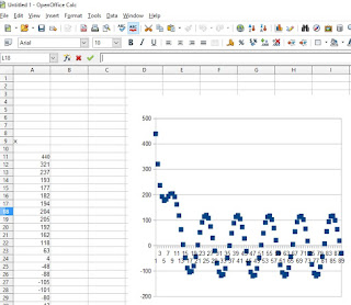
Now, after I played the tones and measured it using the Arduino program, I tried to plot the values using OpenOffice Calc:

We can clearly see that the FFT works as shown by the rise on the magnitude on 200Hz, 625Hz and 850Hz. :)

The three different sine waves are: 200Hz, 625Hz and 850Hz. I also opened the built-in Frequency Analyzer of Audacity for us to have an idea of what those 3 frequencies are.
This is the code that I wrote for Arduino http://codepad.org/UnFPb87k
On the code, notice that I used 450usec on the delay. This value is ideal for the 3 target frequencies that I will generate from Audacity and this is the explanation: The FFT bin size is 256. The output array will be FFT bin size divided by 2 (256/2 = 128). In this case, my array dimension is from 0 to 127.
@ array 0, index * (1/T) / binsize = 0 * (1/450usec) / 256 = 0 Hz
@ array 1, 1 * (1/450usec) / 256 = 8.680555555555555 Hz
@ array 2, 2 * (1/450usec) / 256 = 17.36111111111111 Hz
@ array 127, 127 * (1/450usec) / 256 = 1102.4305555555554 Hz
Which means, I will be measuring only up to 1102 Hz.
Now, after I played the tones and measured it using the Arduino program, I tried to plot the values using OpenOffice Calc:

We can clearly see that the FFT works as shown by the rise on the magnitude on 200Hz, 625Hz and 850Hz. :)
Arduino Signal Experiment #1 Sine Wave Input to Arduino using Laptop Speaker
Most of us who would like to do actual experiments for FFT or Goertzel algorithms using Arduino will need a simple signal generator to be fed into the analog pins of Arduino. We could buy some cheap signal generators from Ebay or Aliexpress, but there is a cheaper alternative that is already in front of you.... your PC or Laptop's Speaker output. In this blog post, I will show a step-by-step guide on how to use this.
Our PC or Laptop's speaker output has a DC offset of 0V(due to AC coupling) as seen on majority of audio designs. This means that the sine wave can reach down to negative voltage which is not an ideal input to Arduino since it will not be able to measure the negative voltages. To resolve this, the sine wave must have a DC offset to be able to read the positive and negative peak of the sine wave. Here is a simple circuit to do that:

On the simulation, we can see that the input V_speakerInput was offset to Vcc/2. On the actual circuit, the R4 must be removed since it was only placed here to act as a dummy load (some simulators have trouble simulating circuit without load). The R1 and R2 can range from 1K to 3K. The R3 can range from 100 to 470 ohms. Here is the actual circuit:

I am using the great Arduino Mega 2560 and I soldered the surface mount resistor and capacitor on a separate bare PCB board. As you notice, there is only 1 wire from the TRRS audio jack that I used. This is because I omitted the ground wire to avoid ground loop. I will just simply use the USB's ground as the main ground source of the circuit.
Next part is the software to generate the sine wave -----> the great open source Audacity. This is a beautiful piece of software which I use most of the time for music recording/composition. I never expected to use this someday on my engineering work as well. :) Going to back to our project, once you run Audacity, go to Generate menu > Tone and you can see that:

For the Arduino, here is the code that I am using currently using to verify if Arduino can read the sine wave (with DC offset) http://codepad.org/infZ2OLV
To prove that it works, I generated a sine wave tone on Audacity at 400Hz. I captured it using Arduino and graphed it:

Voila! A sine wave with DC offset. :)
Our PC or Laptop's speaker output has a DC offset of 0V(due to AC coupling) as seen on majority of audio designs. This means that the sine wave can reach down to negative voltage which is not an ideal input to Arduino since it will not be able to measure the negative voltages. To resolve this, the sine wave must have a DC offset to be able to read the positive and negative peak of the sine wave. Here is a simple circuit to do that:

On the simulation, we can see that the input V_speakerInput was offset to Vcc/2. On the actual circuit, the R4 must be removed since it was only placed here to act as a dummy load (some simulators have trouble simulating circuit without load). The R1 and R2 can range from 1K to 3K. The R3 can range from 100 to 470 ohms. Here is the actual circuit:

I am using the great Arduino Mega 2560 and I soldered the surface mount resistor and capacitor on a separate bare PCB board. As you notice, there is only 1 wire from the TRRS audio jack that I used. This is because I omitted the ground wire to avoid ground loop. I will just simply use the USB's ground as the main ground source of the circuit.
Next part is the software to generate the sine wave -----> the great open source Audacity. This is a beautiful piece of software which I use most of the time for music recording/composition. I never expected to use this someday on my engineering work as well. :) Going to back to our project, once you run Audacity, go to Generate menu > Tone and you can see that:
- You can generate Sine/Sawtooth/Squarewave
- You can set the amplitude and time duration
- You can even produce and mix different tones and play them all together!

For the Arduino, here is the code that I am using currently using to verify if Arduino can read the sine wave (with DC offset) http://codepad.org/infZ2OLV
To prove that it works, I generated a sine wave tone on Audacity at 400Hz. I captured it using Arduino and graphed it:

Voila! A sine wave with DC offset. :)
Thursday, 11 February 2016
MyHDL Project #2: Flexible Multiplexer Demultiplexer
https://github.com/fwswdev/MyHDLCollection/blob/master/02_FlexibleMuxDemux.py
This is a MyHDL program that contains multiplexer and demultiplexer. They both share a group of select pins. Users can change the number of mux and demux by just simply changing the BIT_WIDTH constant.
Few years back, I designed a UART Multiplexer/Demultiplexer using lots of 74HC4051. If I only knew MyHDL and XC2C128 by that time, my design could have been more compact. :)
MyHDL Project #1: Two Counters with 2 to 1 Multiplexer
Recently, I had been studying MyHDL with Xilinx CoolRunner XC2C128 CPLD. MyHDL is a very good software. I can simply reuse my existing Python skills and get started quickly with HDL designs.
https://github.com/fwswdev/MyHDLCollection/blob/master/01_TwoBlinkingLightsWith2to1Mux.py
This is a MyHDL program that has two counter (fast and slow) that outputs square waves. The counters are being controlled by a rising edge clock signal coming from a square wave signal generator (on my experiment, I used a 555 timer on astable mode). It is then fed into a 2 to 1 mux. This is tested working with XC2C128, Xilinx ISE 14.7, and Bus Pirate as the programmer.
This is the resulting test bench waveforms (I modified the internal counters to 5 and 10)

Special Thanks to this Online Wave Viewer http://www.edaplayground.com/w/home
Subscribe to:
Comments (Atom)